
Introduction
Modern electronic equipment depends on a stable and reliable power supply to operate correctly. However, the electricity supplied by an AC source must often be converted into direct current (DC) before it can power electronic circuits. This process is known as rectification, and bridge rectifiers play an important role in making it possible. From consumer electronics and industrial control systems to power adapters and household appliances, these components help convert alternating current into a form that electronic devices can use.
Good-Ark offers standard bridge rectifiers across different package families, helping engineers compare component specifications and identify suitable options for their designs. By understanding how bridge rectifiers work, their key electrical ratings, and their role in power conversion, designers can make informed decisions that support reliable equipment performance.
Understanding How Bridge Rectifiers Work
A bridge rectifier is an electronic component that uses four diodes arranged in a bridge circuit to convert AC input into pulsating DC output. Alternating current changes direction periodically, while direct current flows in one direction. The bridge circuit guides current through the load in the same direction during both halves of the AC cycle. This process is called full-wave rectification because it uses both the positive and negative portions of the input waveform. Compared with half-wave rectification, which uses only one half of the AC cycle, a full-wave bridge rectifier makes better use of the available input and produces a higher average DC output under comparable conditions.
Bridge rectifiers are widely used because they offer a practical way to simplify AC-to-DC conversion. In many applications, the rectifier is placed after a transformer or another AC source and before a filter capacitor or voltage regulator. The capacitor helps smooth the pulsating output, while a regulator can provide a more stable DC voltage when the circuit requires it. Good-Ark bridge rectifiers give designers a range of component options to evaluate for these power supply stages. Selecting the correct device requires more than checking its package or nominal current rating. Engineers should also consider input voltage, expected load, heat generation, surge conditions, and the electrical needs of the complete circuit.
Key Electrical Ratings for Bridge Rectifier Selection
Choosing bridge rectifiers starts with understanding their main electrical specifications. The maximum repetitive reverse voltage indicates how much reverse voltage a device can withstand repeatedly under specified conditions. The average forward current rating describes the current the rectifier can carry when used within its stated thermal and electrical limits. Surge forward current is another important specification because power circuits may experience brief current peaks when they start, especially when large capacitors are connected to the output. Forward voltage drop also matters because current flowing through the internal diodes produces a voltage loss and generates heat. Reviewing these values together helps engineers select components that match both normal operation and expected electrical stress.
Temperature limits are equally important when evaluating Good-Ark bridge rectifiers for real-world applications. A component’s current capability can depend on its operating temperature, mounting method, and ability to transfer heat into the surrounding environment. Designers should review the datasheet to understand the stated ratings, test conditions, thermal resistance, and any derating requirements. A rectifier that appears suitable based on current alone may not perform as expected if it operates in a hot enclosure or has limited airflow. Comparing voltage ratings, current ratings, surge capability, forward voltage, and temperature limits provides a more complete view of component suitability. These specifications help narrow the choices before engineers conduct further circuit analysis and testing.
Package Families and Their Role in Electronic Design
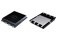
The physical package is another important factor when choosing bridge rectifiers. Different package families support different board layouts, assembly methods, and thermal requirements. Compact packages can be useful in space-limited consumer products, while larger packages may provide mounting options or thermal characteristics better suited to specific power applications. Package selection also affects the circuit board footprint, component spacing, electrical connections, and manufacturing process. Before choosing a part, engineers should confirm its dimensions, pin configuration, polarity markings, and recommended mounting conditions. These details help reduce design errors and make it easier to integrate the rectifier into the intended equipment.
Good-Ark’s standard bridge rectifier catalog provides a starting point for comparing components across available package families. Rather than selecting a device based only on appearance or a single headline specification, engineers can compare the electrical and thermal data that matter to their application. A compact power adapter, for example, may place greater emphasis on board space and temperature control, while industrial equipment may require careful attention to voltage stress, load current, and surge conditions. In either case, the best choice depends on the complete design. Reviewing the relevant product information and datasheet helps confirm whether a candidate component meets the required limits and fits the intended assembly.
Applications and Design Considerations for Reliable Power Conversion
Bridge rectifiers support a wide range of electronic applications, including power adapters, household appliances, lighting equipment, industrial control units, and general-purpose DC power supplies. In each application, the rectifier serves as one stage of a larger power conversion system. Its performance can affect power losses, heat generation, and the quality of the DC output delivered to the next circuit stage. Engineers should consider the expected AC input range, load variations, ambient temperature, and possible startup surges when choosing a component. They should also evaluate the filter capacitor, voltage regulator, transformer, and protective components as part of the same design instead of treating the bridge rectifier as an isolated part.
Good-Ark’s development as a diode enterprise reflects a long-term focus on semiconductor components and continued growth. The company’s history describes a journey from a small factory to a recognized supplier, supported by the work of employees, customers, and partners. Its stated values emphasize employee well-being, customer appreciation, learning, and cooperation. For engineers and purchasing teams, these principles provide useful company context when exploring the Good-Ark product range. Technical selection, however, should always rely on current product documentation and application requirements. By checking datasheets, confirming package compatibility, and allowing suitable electrical and thermal margins, design teams can make better-informed decisions when integrating bridge rectifiers into dependable electronic equipment.
Conclusion
Bridge rectifiers simplify AC input conversion by directing current through a load in one direction during both halves of an AC cycle. Their straightforward operation makes them valuable in power supplies and many types of electronic equipment. However, reliable performance depends on choosing a component with suitable voltage, current, surge, forward voltage, temperature, and package specifications.
Good-Ark’s standard bridge rectifier catalog helps engineers compare available options and identify candidate parts for further evaluation. By reviewing the relevant datasheets, understanding the operating environment, and considering the complete power supply design, engineers can select bridge rectifiers that meet their application needs. A careful selection process supports efficient power conversion, effective thermal management, and dependable equipment operation over time.